Removal of the corrector plate is something that I would try and avoid doing if possible, however, sometimes things happen which mean that action has to be taken. The choice is then whether to send the instrument to be repaired / cleaned by someone else, or to do it yourself. There is obviously risk if you do the work yourself in that if it goes wrong it is you own responsibility. I have sent a telescope off previously to be cleaned and not been happy with the result, so in my case I felt that I could probably do a better job.
The problem that had arisen is that I had a patch of mould growing on the primary mirror. Originally a very small spot of grease had fallen onto the mirror from the baffle. This had given a focal point for dew to form on, and over time mould had somehow started to grow on it. I ignored this as long as I could, but eventually it got to a point where I felt I had to take action. A word of warning here, the primary mirror coating is very very delicate and I really would not advise cleaning it if at all possible. In the process of removing the mould (which was really well stuck) I managed to put 3 very small, random well spaced scratches in the mirror, however, I have been unable to detect any change in performance of the telescope, so I seem to have got away with it this time.
Tests after re-assembly showed that the telescope was still perfectly collimated which I have to admit was a surprise, but very welcome! What follows is a description of the removal of the CGE corrector plate.
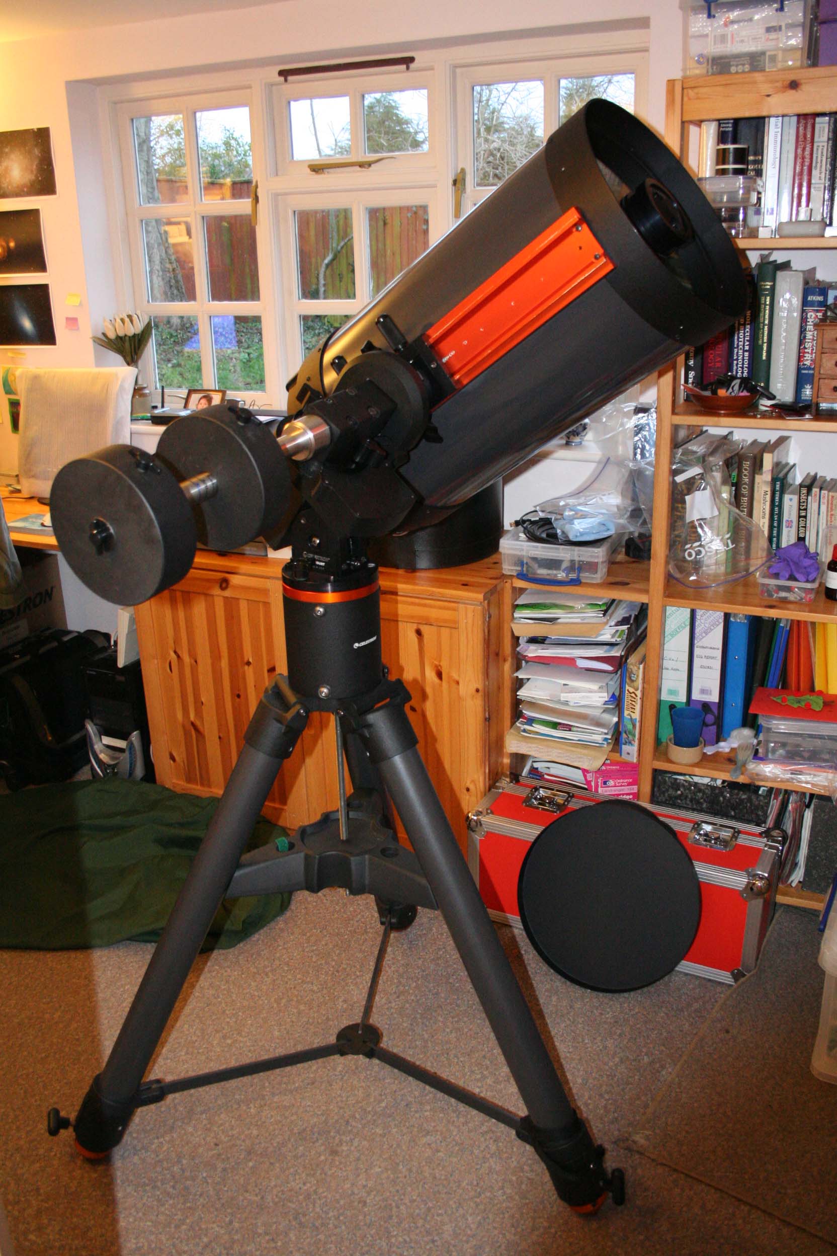
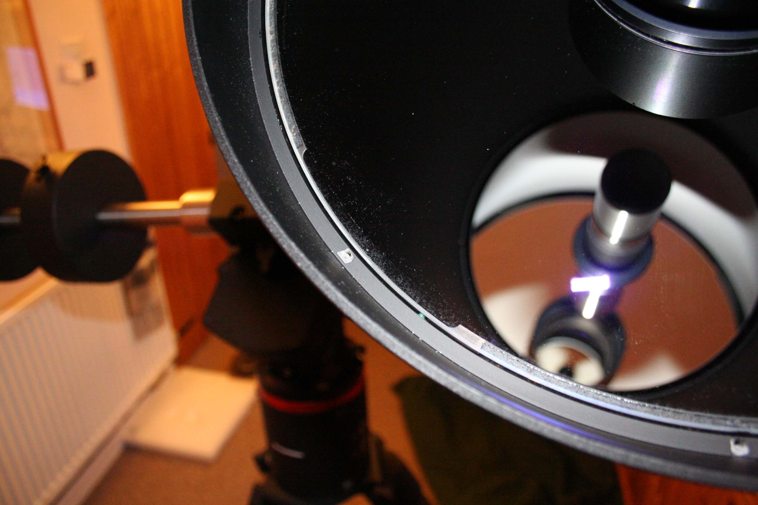
Set the telescope up at an angle of about 45' as shown. This allows you to remove the collar ring and the corrector plate stays in place, ie will not fall out.
Careful observation of the position of the corrector plate showed that it was resting on the green capped screws on the left, but not on the right. On the right hand side there was a gap between the corrector plate and these screws.
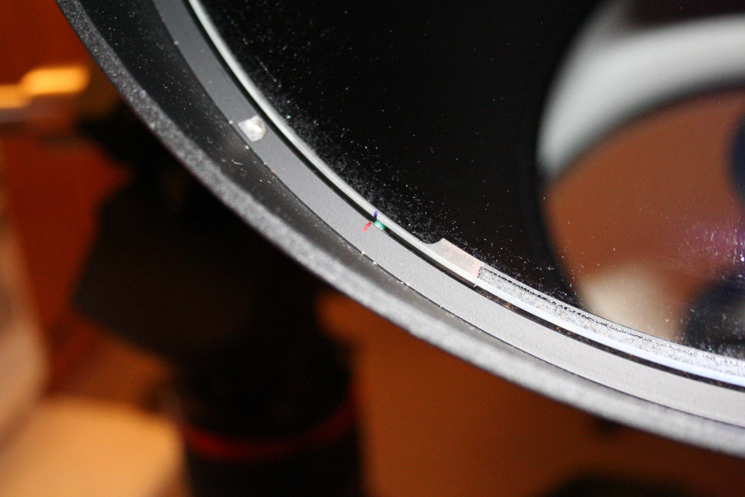
It could be seen that the corrector plate was resting on cork and again seemed to be covered in the sticky black stuff.
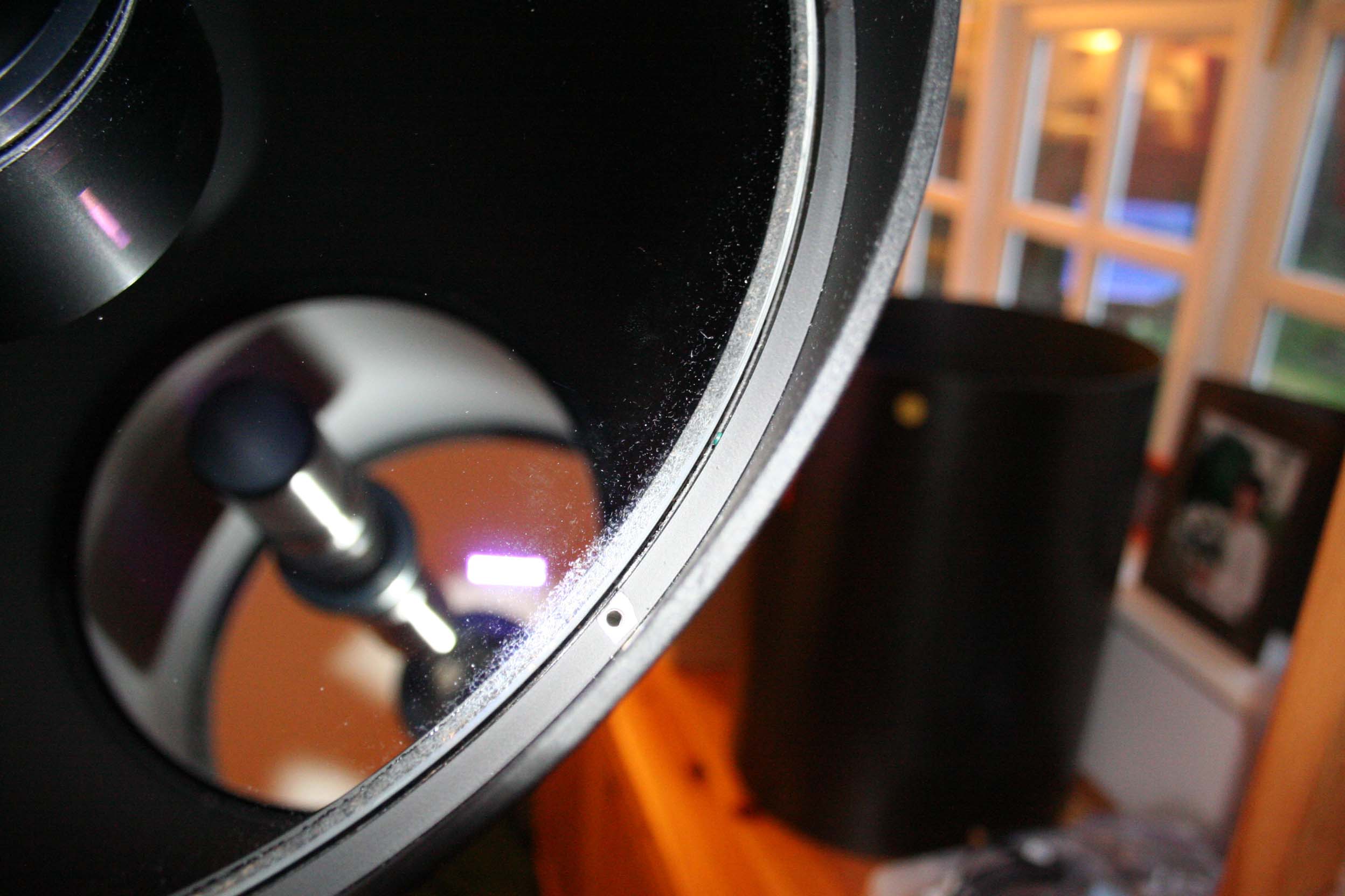
The position of the corrector plate was noted for reference during re-assembly.
The position of the corrector plate was then marked with pen on the edge of the corrector plate and on the tube ring. The mark shown here is adjacent to one of the green capped screws mentioned above.
The corrector plate could then be carefully lifted out holding it by the secondary mirror housing.
I wore nitrile gloves while handling the corrector plate to prevent finger marks. The corrector plate could be rested on a clean surface on the secondary mirror housing as shown.
Re-assembly was the reverse of this procedure.
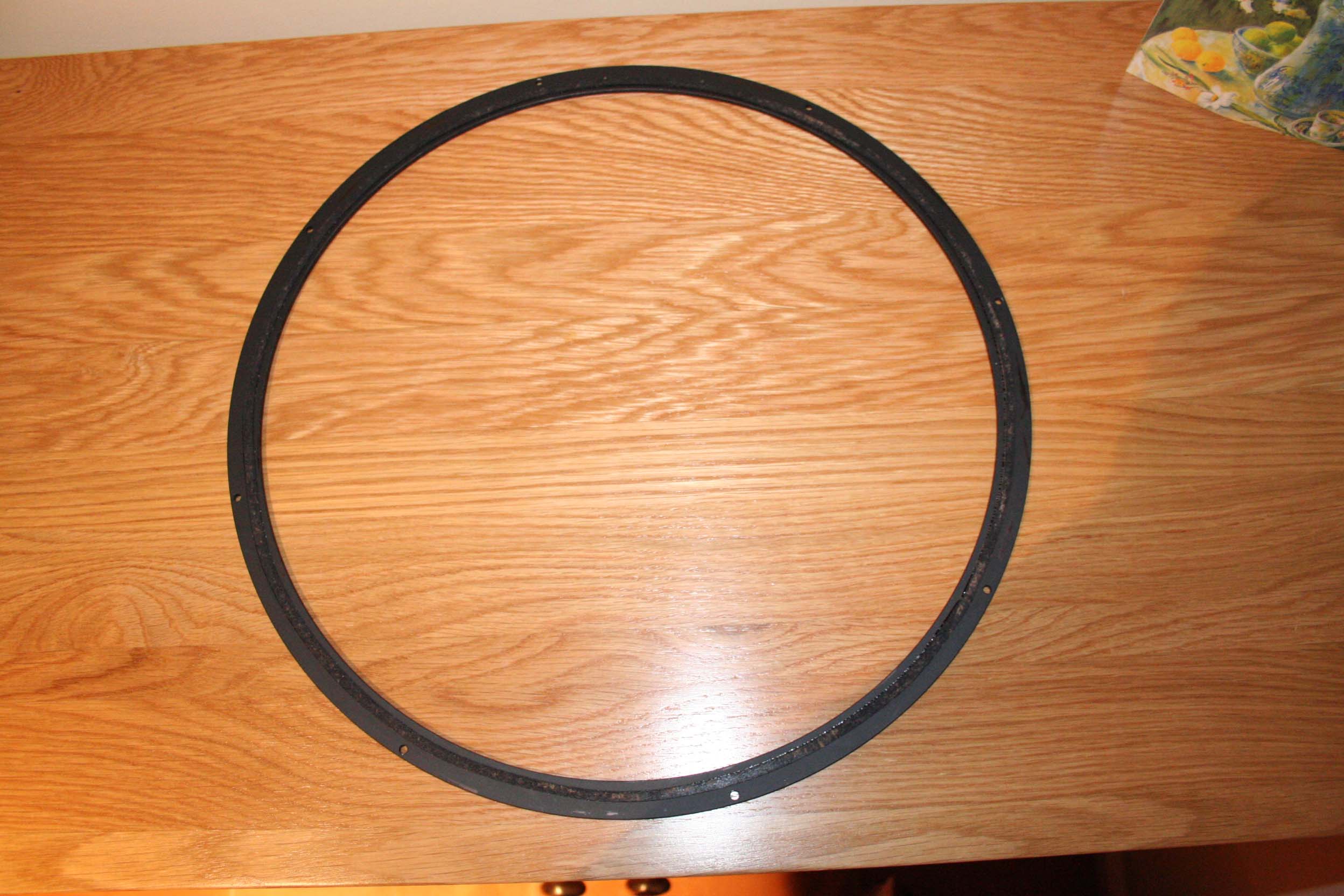
Shown here are the eight screws that hold the collar in place. The collar holds the corrector place in. I marked the position of the collar with a marker pen just in case the screws are not quite evenly spaced round the ring. They look as if they are, but better safe than sorry. I then removed the eight screws.
The collar could then be carefully lifted out. There is a cork ring that runs round the inside which has some sort of black sticky material on it.